
Magnetic Material Power Tester:What is a magnetic material power tester and why is it important for engineers?
Q: What is a magnetic material power tester and why is it important for engineers?
A: A magnetic material power tester is a specialized instrument used to measure power losses in magnetic components such as inductors, transformers, and chokes under real-world operating conditions. Unlike simple inductance meters, these testers apply AC excitation at various frequencies and flux densities, then measure core loss, copper loss, and total power dissipation. Engineers rely on them because magnetic materials like ferrites, powdered iron, and nanocrystalline alloys exhibit complex behavior that varies with frequency, temperature, and DC bias. Without accurate power loss data, power supply designs can overheat, fail efficiency targets, or become larger than necessary. A good tester helps optimize core selection, winding geometry, and thermal management, directly impacting energy efficiency and reliability. Whether you're designing a switch-mode power supply, an EV traction inverter, or a wireless charging coil, a magnetic material power tester provides the empirical data needed to validate simulations and meet regulatory standards like DOE Level VI or EU CoC Tier 2.
Q: How does a magnetic material power tester measure core loss, and what key parameters should users monitor?
A: Most magnetic material power testers use a combination of a power analyzer and a high-frequency excitation source. The device applies a sinusoidal or square voltage to a primary winding, measures voltage and current with high bandwidth, and calculates instantaneous power. Core loss is derived by subtracting copper loss (I²R) from total measured power. Critical parameters to monitor include excitation frequency (typically 10 kHz to several MHz), peak flux density (Bmax), duty cycle, and temperature. Many advanced testers also offer DC bias capability to simulate conditions in inductors carrying DC current. Users should watch for phase shift accuracy and probe calibration, as small errors in phase can cause large errors in loss measurement. Additionally, keeping the test fixture's parasitic capacitance low is essential for high-frequency accuracy. Understanding these parameters allows engineers to create loss maps (e.g., Steinmetz parameters) for simulation models, ensuring that the final magnetic design performs as predicted across the entire operating range, from light load to full load.
Q: Can a magnetic material power tester help with compliance testing and thermal design of magnetic components?
A: Yes, it is indispensable for both compliance and thermal design. Regulatory bodies like the U.S. Department of Energy and the European Union set strict efficiency standards for power supplies and adapters. A magnetic material power tester lets you measure no-load and full-load losses to verify compliance before submitting for certification. For thermal design, the tester provides real power loss values that feed directly into thermal simulations or empirical temperature rise tests. Because core loss increases nonlinearly with flux density and frequency, knowing the exact loss at worst-case operating points prevents hot spots and premature insulation failure. Moreover, by sweeping frequency and bias, engineers can identify regions where the material becomes excessively lossy due to domain wall resonance or eddy currents. This data guides the choice of thinner laminations, lower-loss ferrites, or litz wire to reduce AC resistance. Ultimately, using a power tester early in the design cycle reduces prototyping iterations, lowers bill-of-materials cost, and ensures the final product meets both efficiency and thermal reliability requirements.
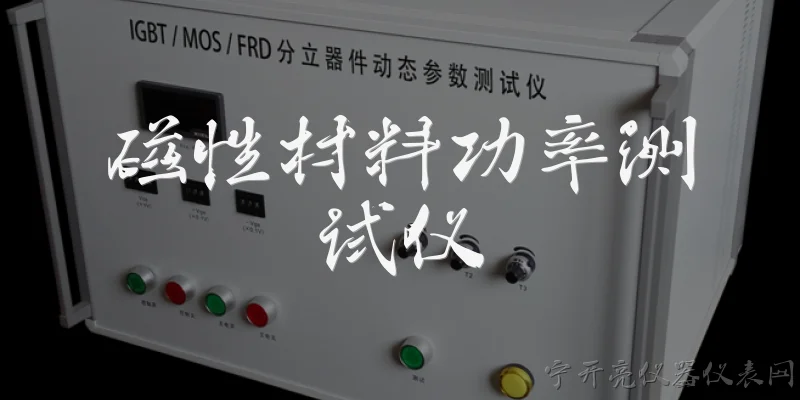
Dialogue about
Common scenarios of "Magnetic Material Power Tester"
【Client】 Hello, we are looking to purchase a Magnetic Material Power Tester for our R&D lab. Can you tell me what this equipment is used for?
【Sales Engineer】 Certainly! A Magnetic Material Power Tester measures core loss, permeability, and other magnetic properties of materials like ferrites, amorphous alloys, and electrical steels. It's essential for designing transformers, inductors, and motors.
【Client】 What frequency range does your tester cover? We work with frequencies from 20 kHz to 1 MHz.
【Sales Engineer】 Our standard model covers 10 Hz to 1 MHz, and we also have a high-frequency version up to 10 MHz. The 20 kHz to 1 MHz range is well within our capabilities.
【Client】 Great. What about measurement accuracy? We need to ensure reliable data for our simulations.
【Sales Engineer】 The accuracy is typically ±1% for core loss and ±0.5% for permeability, depending on calibration. We provide NIST-traceable calibration certificates.
【Client】 Can it measure both toroidal and planar cores? Our designs include both.
【Sales Engineer】 Yes, we offer interchangeable fixtures for toroidal, planar, and even custom geometries. The software allows easy switching between fixture types.
【Client】 What software is included? Is it compatible with Python for automation?
【Sales Engineer】 The included software has a user-friendly GUI and also provides a Python API and LabVIEW drivers. You can automate measurements and export data in CSV or HDF5 formats.
【Client】 That sounds promising. What are the power requirements and dimensions?
【Sales Engineer】 It requires 100-240 VAC, 50/60 Hz, and the main unit is 19-inch rack-mountable, 4U high. The test fixtures are compact and can be placed on a bench.
【Client】 Do you offer on-site training and support?
【Sales Engineer】 Yes, we provide one day of on-site training and a one-year warranty with remote support. Extended service contracts are also available.
【Client】 What is the lead time and price for the high-frequency model?
【Sales Engineer】 Lead time is typically 6-8 weeks. The high-frequency model starts at $45,000 USD, but I can provide a detailed quote based on your specific configuration.
【Client】 Can we schedule a demo before purchasing?
【Sales Engineer】 Absolutely. We can arrange a virtual demo or send a demo unit to your lab for a week. Let me know your preferred dates.
【Client】 We'd like a demo unit. Also, does the tester support DC bias measurements?
【Sales Engineer】 Yes, with an optional DC bias current source, you can measure up to 100 A of DC bias. This is crucial for inductor design under saturation.
【Client】 Perfect. We also need to measure temperature-dependent properties. Can it interface with a temperature chamber?
【Sales Engineer】 Yes, the software supports communication with temperature chambers via GPIB or Ethernet, allowing automated temperature sweeps from -40°C to 200°C.
【Client】 That covers our needs. Please send a formal quotation with the high-frequency model, DC bias option, and temperature chamber interface.
【Sales Engineer】 I'll prepare and send the quotation by tomorrow. Thank you for your interest!